This is a how I managed to launch the Openmower on Yard force SA900ECO mower by using Mowgli
Note that SA900ECO casing is a bit different from the Classic 500 therefore the part list is a bit different. My main goal was to do it as cheap as possible
Warning
Use is this as a guideline only. I have not done much field testing with given hardware setup, so it’s better to stick to the original (RPI4 + ArduSimple RTK).
And as usual - your warranty is void, if you mess up you can burn everything
Note
I take no credit for this - all effort done by the community of Openmower, I just documented the steps I took to launch Openmower on SA900ECO
Price Breakdown
- Yard force SA900ECO mower 299€ (Used, Amazon Warehouse) + 26€ shipping
- DC-DC LM2596 Step Down 1.84€
- ST-LINK v2 clone 2.79€
- Orange PI Zero 3 4GB 36.38€
- UM626N RKT GPS L1/L5 module 77.84€
- L1/L5 GNSS antenna 16.57€
- MPU6050 IMU Gyro Sensors + Accelerometer 1.68€
- ATX EPS 8pin male,EPS 8pin female 2.52€
- JST 2.0mm step 4 and 9 pin cables 4.97€
Other parts that I already had: USB2TTL adapter, SMA-IPEX adapter, Wifi antenna, various cabling
Total: 469.59€
Notes about parts
DC-DC
My initial plan was to use the more powerful DC-DC step down converter but I found it hard to fi into the SA900ECO casing. Some people have reported that LM2596 is not stable, but form my limited testing I have not experienced any issues with Orange PI Zero 3
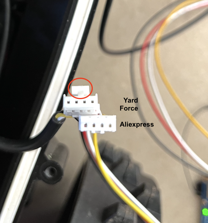
JST cables
I actually bought these JST cables while they do fit, they are not the ones used by Yard Force, the “click” is missing
ATX EPS 8pin male,EPS 8pin female
This cable is only needed if you don’t want to splice the original one (e.g. for warranty purposes)
Orange PI Zero 3
This board has too many shortcoming to justify it’s usage with current Raspberry PI4 price. At the time of purchase this was 36€ vs 86€ so it kind of made sense. Currently RPI4 is 51€ shipped vs 41€ for Orange PI Zero 3. Yet Orange PI Zero 3:
- has only 1 attached USB port and 2 via pinouts. I ran out of USB ports and was not able to plug in the Joystick for testing
- UART is only one, and I was not able to get it above 115200bps, so not usable for RTK GNSS, only for debug console
UM626N RTK GNSS
With current cheap antenna the UM626N seems to be somewhat working - meaning that it takes 1-2h to get an RTK Fix (not RTK float) and I have not tested that in hard conditions (near the fence, near the house, high trees, etc.) So if it is a stable solution long term remains to be seen. My plan is to update to Helix type antenna (HX-901 or HA-901) and see if that helps. For the time being you should stick to the expensive ArduSimple RTK board
Taking the Mower apart
Turn it over and unscrew the screws.
- Remove the blades, you don’t want any to mess with those:)
- The four big ones (marked in blue) will detach the outer shell.
- The smaller ones (marked in red) will allow you to access boundary sensor and charging, stop wires.
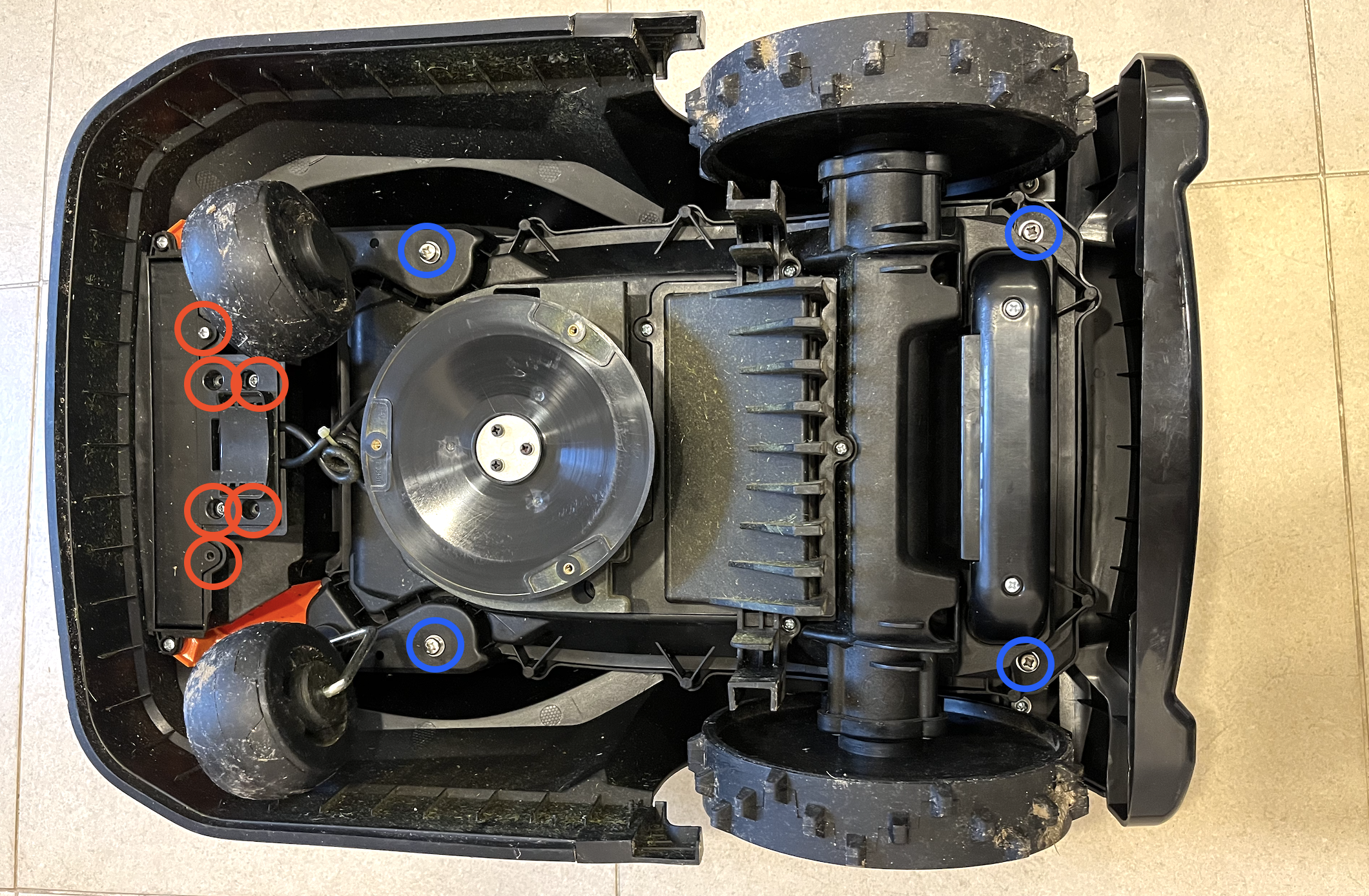
Disconnect the wires:

The outer shell should detach and you should be left with the mower itself.
Now you need to:
- Unscrew the panel (marked in yellow) and disconnect the gray cable
- Unscrew the mower motor height adjuster (marked red) and gently pull it off
- Unscrew the perimeter of the mower casing (marked blue)
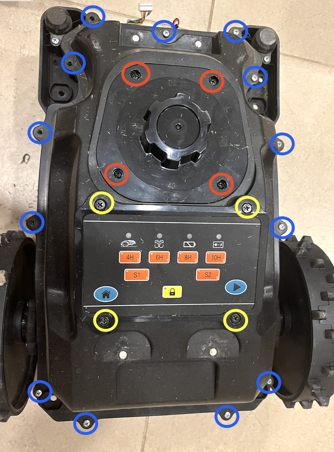
Take a long screwdriver and unscrew the mower upper case
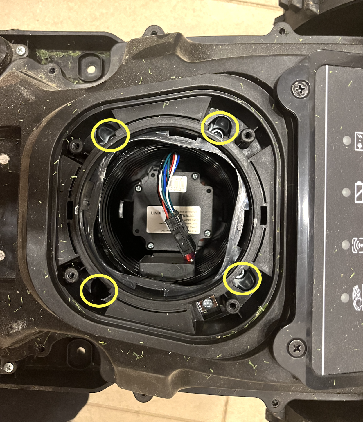
You should now have full access to the mainboard
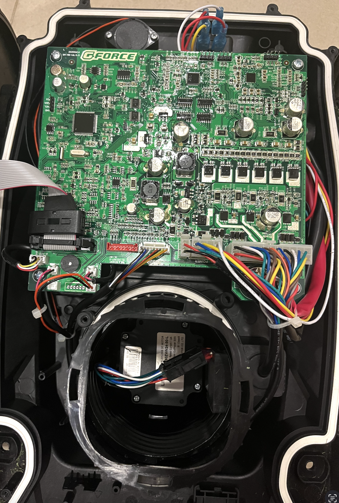
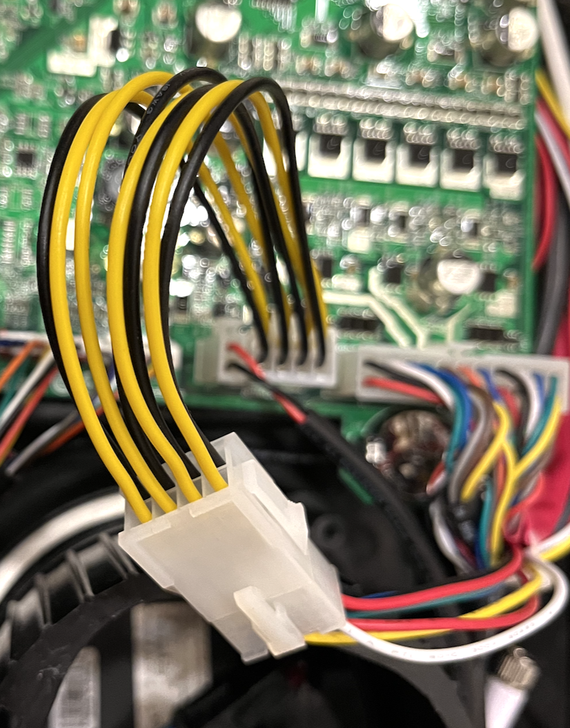
The motherboard connectors
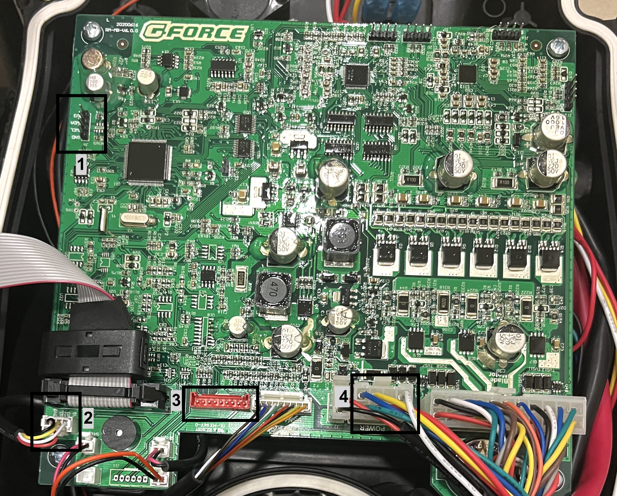
We will be using 4 connectors on the motherboard:
- J9 st-link will be wired here and will be used to flashing mower into original mainboard
- J4 Orange PI will be wired here and Mowgli will use this USB interface to control the mower. Original cable must be disconnected (by default it goes to the bottom of the mower where we have an USB port)
- J18 IMU will be wired here and the debug UART cable to the Orange PI
- The Power connector. The Yellow wire is a positive and the Black wire (not visible) is the negative 28v (always check it with the multimeter!) for which we will use to power the DC-DC by inserting ATX EPS 8pin->8pin cable (or you can just cut and solder the current one)
Backup & Flashing Mowgli
So there are couple of options to do that: via st-link via shell, or via Openmower GUI. I took the hard and old approach - compiled the firmware via Vscode platform.io on my laptop, copied the firmware to the Orange PI and used st-link command line to flash it.
Wiring up st-link
You will need to wire st-link to the J9 connector (no 1. in previous diagram) and stick it into the USB port of the Orange PI
Again two options:
- Wire +3v from the st-link and keep the motherboard off
- Do not wire +3v from the st-link, but power up the mower.
For initial flashing I used the +3v from st-link. But the more stable approach would be to power on the mower, and skip +3v connecting (more stable power supply). Just make sure that you charge the mower beforehand
The wiring is as follows
- GND <-> GND
- SWDA <-> SWDIO
- SWCL <-> SWCLK
Preparing the Orange Pi OS
I’ve used Armbian Bookworm (Debian derivative) as an OS
Install st-link
# required libraries for building
apt install git make cmake libusb-1.0-0-dev gcc build-essential libtool libhidapi-dev -y

# get st-link, compile, install
git clone https://github.com/stlink-org/stlink
cd stlink
cmake .
make
make install
ldconfig

# enable /dev aliases
sudo cp stlink/config/udev/rules.d/49-stlinkv* /etc/udev/rules.d/
After completing these steps, check if st-link is alive with st-info --probe command. You should get output similar to this
root@mower:~# st-info --probe
/usr/local/share/stlink/chips: No such file or directory
Failed to enter SWD mode
Found 1 stlink programmers
  version:    V2J34S7
  serial:     B55B5A1A00000000FBC9F001
  flash:      0 (pagesize: 0)
  sram:       0
  chipid:     0x000
Install opencd
apt install openocd -y
Clone the mowgli repo
cd ~
git clone https://github.com/cedbossneo/Mowgli.git
Now we should be ready to backup the original firmware and install mowgli
Creating motherboard backup
So before flashing it would be a great idea to backup the original firmware and store it somewhere safe
cd ~/Mowgli/stm32/mainboard_firmware
./backup_firmware.sh
You should see output similar to this:
root@mower:~/Mowgli/stm32/mainboard_firmware# ./backup_firmware.sh
Open On-Chip Debugger 0.11.0
Licensed under GNU GPL v2
For bug reports, read
	http://openocd.org/doc/doxygen/bugs.html
Info : auto-selecting first available session transport "hla_swd". To override use 'transport select <transport>'.
Info : The selected transport took over low-level target control. The results might differ compared to plain JTAG/SWD
Warn : Transport "hla_swd" was already selected
hla_swd
Info : clock speed 1000 kHz
Info : STLINK V2J34S7 (API v2) VID:PID 0483:3748
Info : Target voltage: 3.228777
Info : stm32f1x.cpu: hardware has 6 breakpoints, 4 watchpoints
Info : starting gdb server for stm32f1x.cpu on 3333
Info : Listening on port 3333 for gdb connections
target halted due to debug-request, current mode: Thread
xPSR: 0x01000000 pc: 0x08000164 msp: 0x20001668
dumped 262144 bytes in 3.159835s (81.017 KiB/s)
You should now have the firmware_backup.bin file which you should store safely.
Creating panel backup
Though the panel will not be flashed, and original comm protocol will be used, it is still recommended to create a backup.
You must now wire the st-link to the panel (same pinout) and backup the panel. You can find more info on the github readme
cd ~/Mowgli/stm32/panel_firmware
./backup_firmware.sh
You should see output similar to this:
root@mower:~/Mowgli/stm32/panel_firmware# ./backup_firmware.sh
Open On-Chip Debugger 0.11.0
Licensed under GNU GPL v2
For bug reports, read
	http://openocd.org/doc/doxygen/bugs.html
Info : auto-selecting first available session transport "hla_swd". To override use 'transport select <transport>'.
Info : The selected transport took over low-level target control. The results might differ compared to plain JTAG/SWD
Warn : Transport "hla_swd" was already selected
hla_swd
Info : clock speed 1000 kHz
Info : STLINK V2J34S7 (API v2) VID:PID 0483:3748
Info : Target voltage: 3.272439
Info : stm32f0x.cpu: hardware has 4 breakpoints, 2 watchpoints
Info : starting gdb server for stm32f0x.cpu on 3333
Info : Listening on port 3333 for gdb connections
Info : Unable to match requested speed 1000 kHz, using 950 kHz
Info : Unable to match requested speed 1000 kHz, using 950 kHz
target halted due to debug-request, current mode: Thread
xPSR: 0xc1000000 pc: 0x080000c8 msp: 0x20001c68
You should now have the panel_controller_backup.bin file which you should store safely.
Verify sha256 checksum
Verify the checksum and see if they match with the ones on the github page
Mine didn’t :) But repeating the backup yielded same results, so somehow I left it as is
root@mower:~/Mowgli/stm32/mainboard_firmware# sha256sum firmware_backup.bin
1f83173e752b83a49f44c117538668d8b5e6be04f88f348989ee02038e519add  firmware_backup.bin
root@mower:~/Mowgli/stm32/panel_firmware# sha256sum panel_controller_backup.bin
00f75588237ef93e4afa7104f261ad112ecf7de2c436d5ac807f2985d8963e57  panel_controller_backup.bin
Flashing mowgli
Building on your local machine
Prepare
I’ve chosen to build this on my laptop, scp the firmware and flash from the command line
- Clone the repo to your local machine https://github.com/cedbossneo/Mowgli
- cd into
stm32/ros_usbnodeforlder - launch Vscode
code .
Vscode should have an PlaformIO IDE extension installed
Now for SA900ECO you must edit the board.h file and set the correct panel type. Change it from something like this:
|
|
To something like this:
|
|
Build
Now it’s time to build the mowgli firmware for flashing
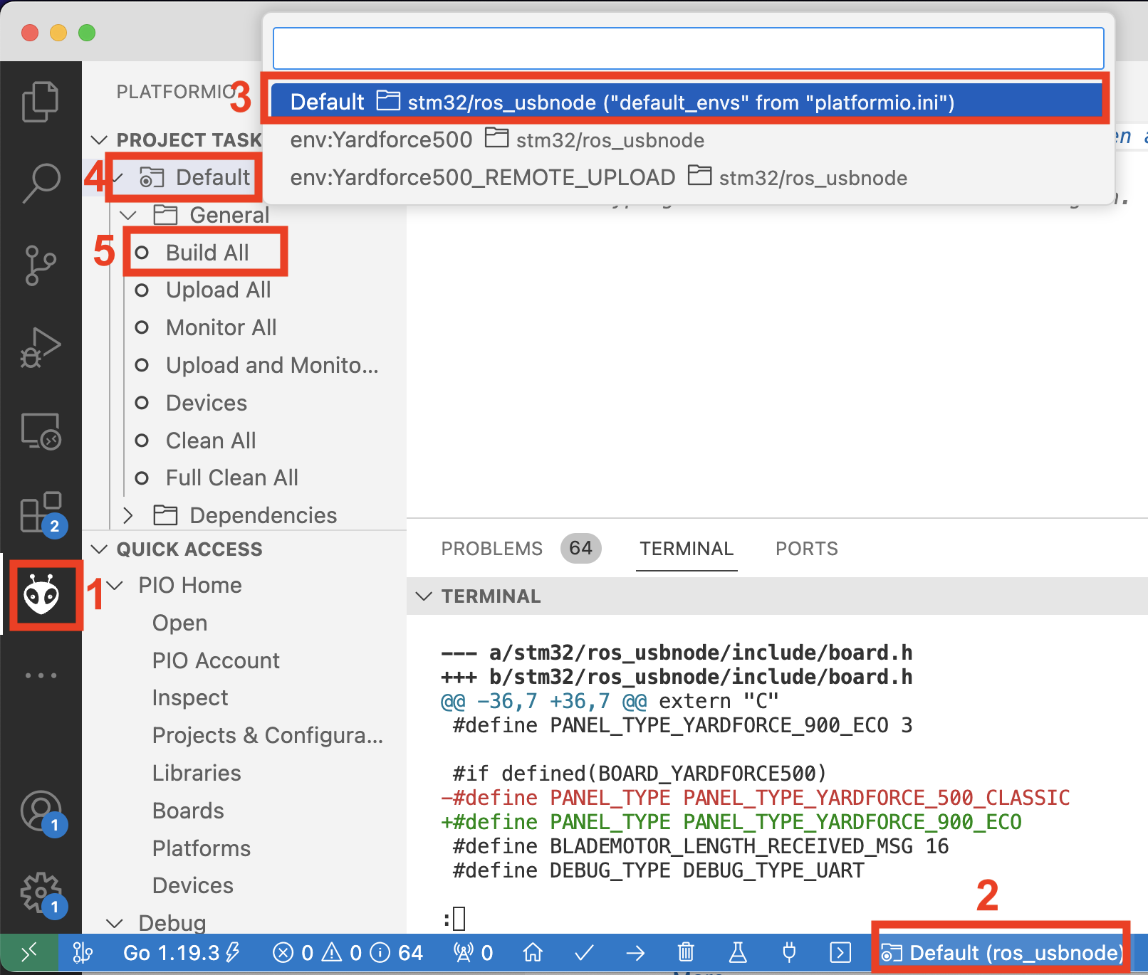
- Ensure that you have the PlatormIO plugin selected
- Click on the bottom project selection
- Ensure that the Default is selected
- Expand Default
- Click Build All
A new terminal should popup and spit out build information:
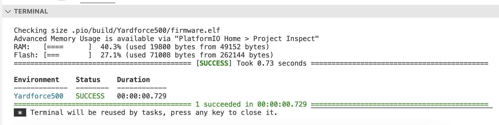
A file .pio/build/Yardforce500/firmware.bin should have been generated which will be used to flash Mowgli
Flash
I’ve flashed the firmware.bin by copying it via scp and then flashing from the command line.
Copy the firmware
scp .pio/build/Yardforce500/firmware.bin mower:
Create yardforce500.cfg on the Orange PI with the following content:
source [find interface/stlink-v2.cfg]
source [find target/stm32f1x.cfg]

transport select hla_swd
Flash!
openocd -f yardforce500.cfg -c " program "firmware.bin" 0x08000000 verify reset; shutdown;"
You should get the following output:
root@orangepizero3:~# openocd -f yardforce500.cfg  -c " program "firmware.bin" 0x08000000 verify reset; shutdown;"
Open On-Chip Debugger 0.11.0
Licensed under GNU GPL v2
For bug reports, read
	http://openocd.org/doc/doxygen/bugs.html
WARNING: interface/stlink-v2.cfg is deprecated, please switch to interface/stlink.cfg
Info : auto-selecting first available session transport "hla_swd". To override use 'transport select <transport>'.
Info : The selected transport took over low-level target control. The results might differ compared to plain JTAG/SWD
Warn : Transport "hla_swd" was already selected
hla_swd
Info : clock speed 1000 kHz
Info : STLINK V2J34S7 (API v2) VID:PID 0483:3748
Info : Target voltage: 3.261905
Info : stm32f1x.cpu: hardware has 6 breakpoints, 4 watchpoints
Info : starting gdb server for stm32f1x.cpu on 3333
Info : Listening on port 3333 for gdb connections
target halted due to debug-request, current mode: Thread
xPSR: 0x01000000 pc: 0x0800c7e0 msp: 0x2000c000
** Programming Started **
Info : device id = 0x10036414
Info : flash size = 256kbytes
** Programming Finished **
** Verify Started **
** Verified OK **
** Resetting Target **
shutdown command invoked
The mower should reboot and you should hear two chirping sounds. And then the chirping should be constant because of emergency mode.
Emergency Mode
Since the outer shell is disconnected Mowgli enters emergency mode because all safety features are triggered:
- left and right wheels - because the magnets that turned off those sensors are on the outer shell
- emergency button which is also on the outer shell
To disable those you either have to:
- re-connect the outer shell
- shorten the wheel and emergency button connectors (not that easy on SA900ECO)
- re-flash the firmware with the funny
I_DONT_NEED_MY_FINGERSdef enabled in the board.h
For initial testing I had I_DONT_NEED_MY_FINGERS (with the blades off!!!) but after that re-flashed and just kept the outer shell on.
Wiring up remaining components
Now it’s time to wire everything up (DC-DC, RTK GNSS, IMU) and test the mower.
Discord user kombo-kevinmce has made a very nice graph indicating how you can wire the RPI4 so you can use that as a guideline
Orange PI Zero 3 Pinout
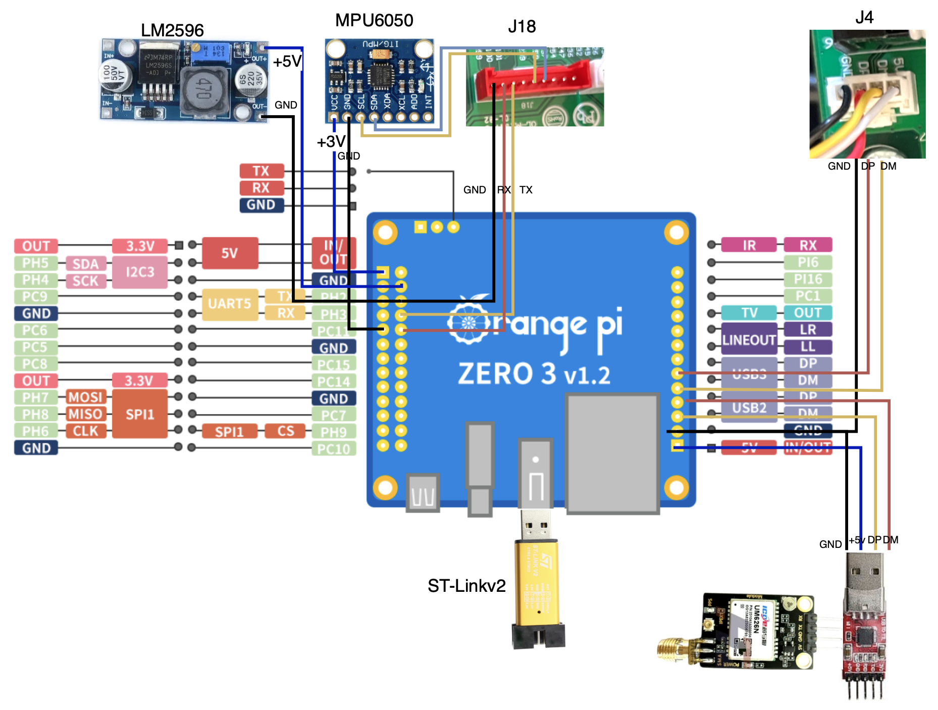
J4 - Controlling the Mower
USB Interface to control the mower. Unplug the original cable, a plug a new one soldered to the USB2 (or USB3, does not matter) Orange PI Zero 3 pins. Leave USB power disconnected
- GND <-> GND
- DP <-> DP
- DM <-> DM
UM626N GNSS
for 10hz updates we need 460800bps baud rate on the UART, and I was not able to get that working. So used a CH340 USB2TTL converter. I’ve soldered the wires directly, but it’s also possible to use a cut down USB female wire.
- GND <-> GND
- DP <-> DP
- DM <-> DM
- 5v <-> 5v
MPU6050 IMU
Used +3V from Orange PI Zero and then SCL and SDA pins to the J18 pin
- GND <-> GND On the PI
- SDA <-> J18 (pin 6)
- SCL <-> J18 (pin 5)
- VCC <-> +3v On the PI
Debug UART console
Though this is optional, it greatly helps to debug e.g. Emergency or other issues, so highly recommended . For this I used the Orange PI Zero 3 native UART interface
- J18 (pin 1) <-> GND
- J18 (pin 2) <-> RX
- J18 (pin 3) <-> TX
DC-DC LM2596
One option is to power up Orange PI Zero 3 via USBC3 port, but since I did not have a spare one, just used the +5v and GND pins for the out
As for the Power IN I attached the extension ATX EPS 8pin cable, cut it and then wired to the LM2596.
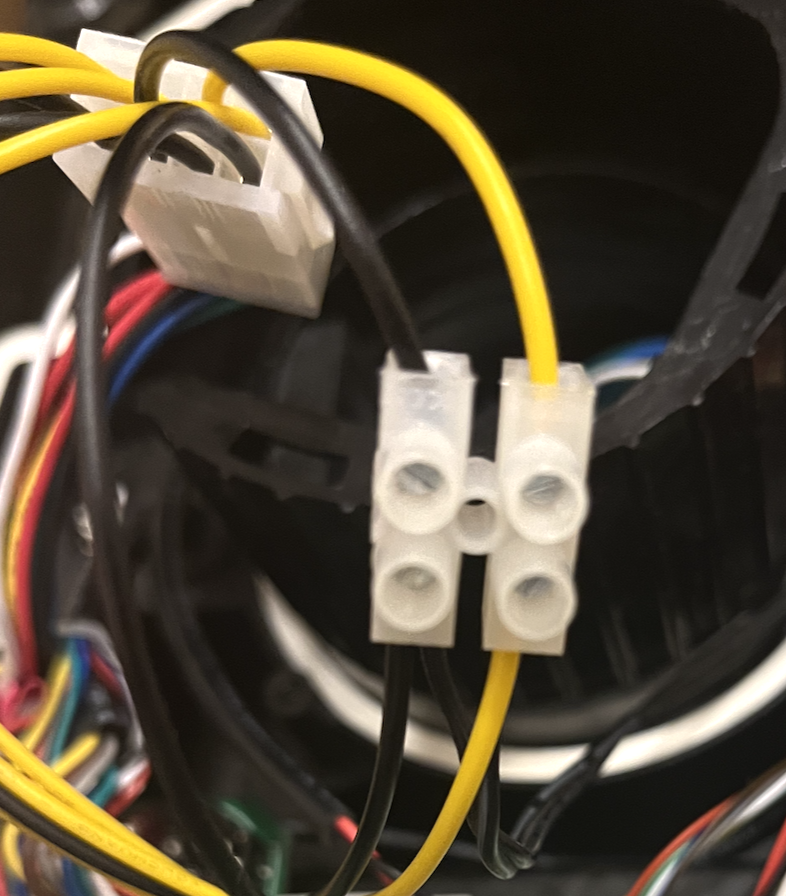
Original Wires on the Yard Force board were Yellow for +28v and Black for GND (but as usual, use your multimeter to check, because the first time I mixed those and LM2596 went up in smoke)
Be sure to adjust the voltage before connecting the Orange PI
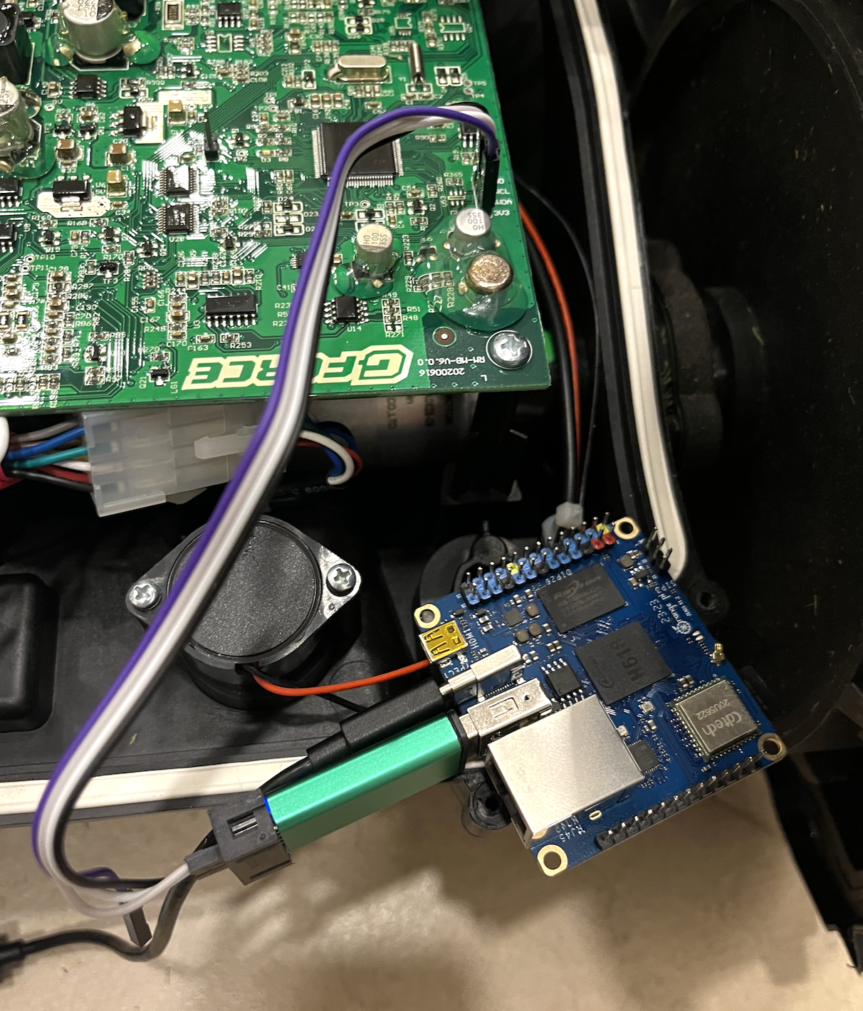
Mounting
I’ve managed to squeeze Orange Pi Zero 3 together with the DC-DC under the mainboard. It looks like it has enough clearance. Additionally added hard on/off switch so I could disconnect the Orange Pi Zero 3 without disconnecting the wires
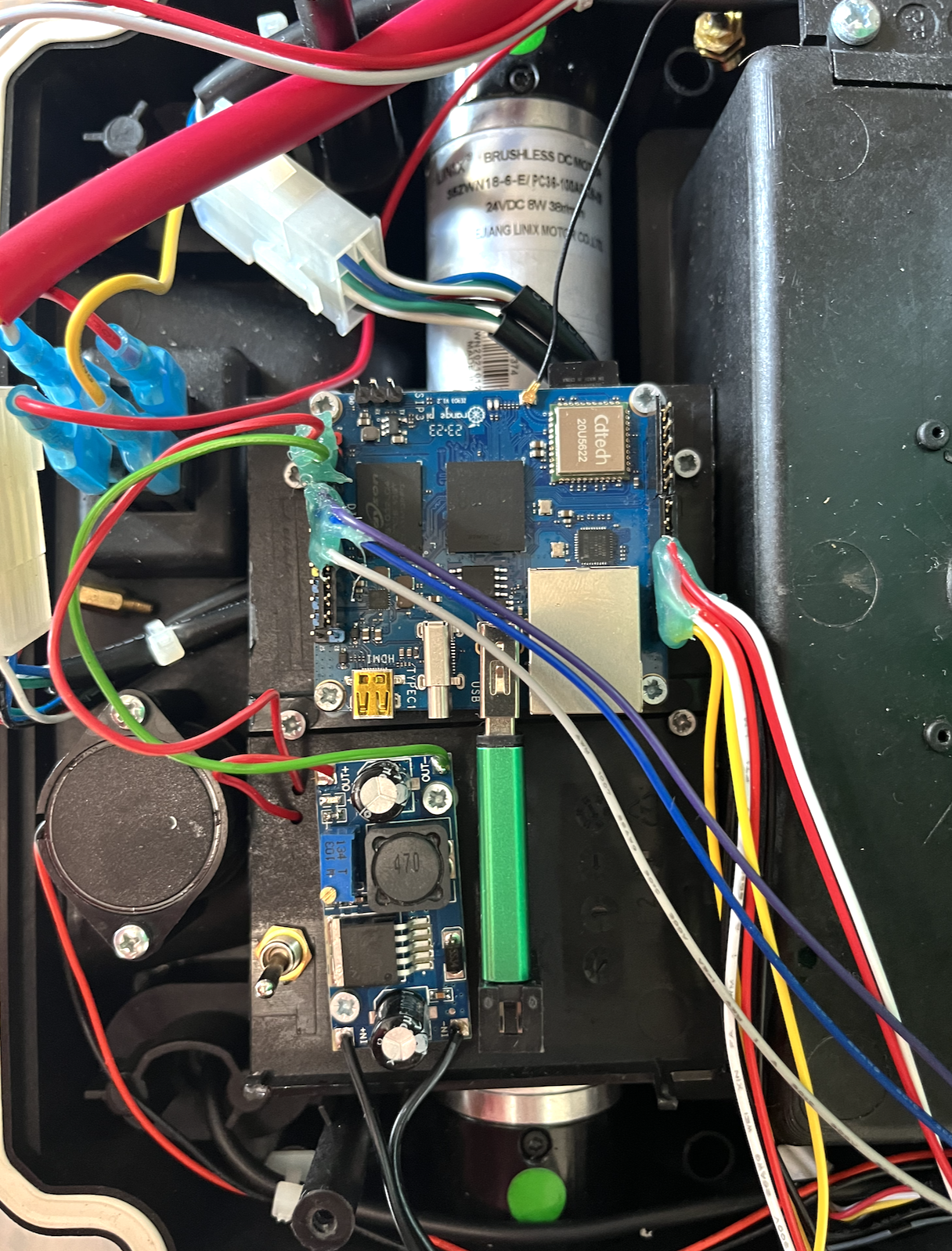
IMU and GNSS were mounted on front. Though for GNSS I’m still thinking what to do and probably change things once I get the Helix antenna
Running
Checking the debug console
Time to actually test if everything works. I like to use picocom as a terminal app to interact with serial devices
apt install picocom -y
Then we can see the output. Since the top cover is removed, it should be flooded with emergency messages:
 ## EMERGENCY ## - STOP BUTTON (yellow) triggered
 ## EMERGENCY ## - WHEEL LIFT (red and blue) triggered
 ## EMERGENCY ## - STOP BUTTON (yellow) triggered
 ## EMERGENCY ## - WHEEL LIFT (red and blue) trigg
If we do a reboot from another terminal
openocd -f yardforce500.cfg -c "shutdown;"
The debug serial should print out the startup info:
    __  ___                    ___
   /  |/  /___ _      ______ _/ (_)
  / /|_/ / __ \ | /| / / __ `/ / /
 / /  / / /_/ / |/ |/ / /_/ / / /
/_/  /_/\____/|__/|__/\__, /_/_/
                     /____/


 * Master USART (debug) initialized
 * LED initialized
 * ADC1 initialized
 * Timer3 (Beeper) initialized
 * 24V switched on
 * RAIN Sensor enabled
 * HALL Sensor enabled
 * Hard I2C initialized
 * Accelerometer (onboard/tilt safety) initialized
 * Soft I2C (J18) initialized
 * Testing supported IMUs:
    > [AltIMU-10v5] - Error probing for LSM6DS33 (Gyro / Accelerometer) at I2C addr=0x6b
    > [WT901] - Error probing for (Gyro / Accelerometer) at I2C addr=0x50
 * MPU 6050 initialized
    > External IMU Calibration started - make sure bot is level and standing still ...
    > External IMU Calibration factors accelerometer [0.089573 -0.135865 0.000000]
    > External IMU Calibration accelerometer covariance diagonal [0.000109 0.482790 3.128996]
    > External IMU Calibration factors gyro [-0.073667 -0.006467 -0.006390]
    > External IMU Calibration gyro covariance diagonal [0.000055 0.000001 0.000001]
 * Panel initialized
 * Emergency sensors initialized
 * Charge Controler PWM Timers initialized
 * Timer1 (Charge PWM) initialized
 * USB CDC initialized
 * Drive Motors USART initialized
 * Blade Motor UART initialized
 * NBT Main timers initialized
 * ROS serial node initialized

 >>> entering main loop ...

 WWDG init Error
 * Drive Motor Controller initialized
 * Blade Motor Controller initialized
 Current ticktime: 101
Lauching mowgli-docker
Now we need to launch the Openmower itself. First I removed the docker that camed with distro and installed new one
apt remove docker-ce-cli docker-ce -y
curl https://get.docker.com | sh
Then let’s clone the mower-dockli repo. I chose to put it under /opt
cd /opt
git clone https://github.com/cedbossneo/mowgli-docker.git
cd mowgli-docker
Adjust the config/om/mower_config.sh file:
export OM_DATUM_LAT=<your_latitude_here>
export OM_DATUM_LONG=<your_longitude_here>
export OM_GPS_PROTOCOL=NMEA #if using GNSS that outpus NMEA
export OM_NTRIP_HOSTNAME=<your_ntrip_host>
export OM_NTRIP_PORT=2101
export OM_NTRIP_USER=<your_ntrip_user>
export OM_NTRIP_PASSWORD=<your_ntrip_password>
export OM_NTRIP_ENDPOINT=<your_ntrip_mount_mount>
I had problems with given docker-compose.yaml, since it does seem that both roscore and openmower want to start rosmaster and if you try to bind to the boards WIFI IP, they do conflict.
So I just removed the roscore service, and everything seems to be working file
My docker-compose.yaml :
version: '3'

services:
  watchtower:
    image: containrrr/watchtower
    restart: unless-stopped
    volumes:
      - /var/run/docker.sock:/var/run/docker.sock
    environment:
      WATCHTOWER_CLEANUP: 'true'   # cleanup old openmower-gui images
      WATCHTOWER_POLL_INTERVAL: 14400   # update check intervall in seconds - eg 14400 = 4h
      WATCHTOWER_DEBUG: 'false'
      WATCHTOWER_LABEL_ENABLE: 'true'
  gui:
    container_name: openmower-gui
    labels:
      "com.centurylinklabs.watchtower.enable": true
      project: openmower
      app: gui
    image: ghcr.io/cedbossneo/openmower-gui:master
    restart: unless-stopped
    network_mode: host
    privileged: true
    environment:
      ROS_IP: ${ROS_IP}
      ROS_MASTER_URI: http://${ROS_IP}:11311
      MOWER_CONFIG_FILE: /config/mower_config.sh
      DOCKER_HOST: unix:///var/run/docker.sock
    depends_on:
      - openmower
    volumes:
      - /dev:/dev
      - ./config/om:/config
      - /var/run/docker.sock:/var/run/docker.sock
  web:
    container_name: mowgli-web
    labels:
      project: openmower
      app: web
    image: nginx
    ports:
      - 4005:80
    volumes:
      - ./web:/usr/share/nginx/html:ro
    restart: unless-stopped

  mosquitto:
    container_name: mowgli-mqtt
    labels:
      project: openmower
      app: mqtt
    hostname: mosquitto
    image: eclipse-mosquitto:latest
    ports:
      - 1883:1883
      - 9001:9001
    volumes:
      - ./config/mqtt/mosquitto.conf:/mosquitto/config/mosquitto.conf:ro
    restart: unless-stopped

  rosserial:
    container_name: mowgli-rosserial
    labels:
      project: openmower
      app: rosserial
    image: ghcr.io/cedbossneo/mowgli-docker:cedbossneo
    network_mode: host
    tty: true
    privileged: true
    logging:
      driver: none
      options:
        max-file: "5"
        max-size: 10m
    environment:
      ROS_MASTER_URI: http://${ROS_IP}:11311
      ROS_IP: ${ROS_IP}
      ROSCONSOLE_CONFIG_FILE: /config/rosconsole.config
      ROSOUT_DISABLE_FILE_LOGGING: true
    command:
      - /opt/ros/noetic/bin/rosrun
      - rosserial_server
      - serial_node
      - _port:=/dev/mowgli
      - _baud:=115200
    tmpfs: /root/.ros/log/
    volumes:
      - ./ros:/root/.ros/
      - ./config/om:/config
      - /etc/timezone:/etc/timezone:ro
      - /dev:/dev
    restart: unless-stopped

  openmower:
    container_name: mowgli-openmower
    labels:
      project: openmower
      app: openmower
    image: ghcr.io/cedbossneo/mowgli-docker:cedbossneo
    network_mode: host
    tty: true
    privileged: true
    logging:
      driver: none
      options:
        max-file: "5"
        max-size: 10m
    environment:
      ROS_MASTER_URI: http://${ROS_IP}:11311
      ROS_IP: ${ROS_IP}
      ROSCONSOLE_CONFIG_FILE: /config/rosconsole.config   # comment this line out to enable more logs
      ROSOUT_DISABLE_FILE_LOGGING: true                   # comment this line out to enable more logs
    tmpfs: /root/.ros/log                          # comment this line out to enable persistent logs
    volumes:
      - ./config/om:/config
      - ./mower_params:/root/mower_params:ro
      - ./params:/opt/open_mower_ros/src/open_mower/params:ro
      - ./ros:/root/.ros/
      - /etc/timezone:/etc/timezone:ro
      - /dev:/dev
    depends_on:
      - rosserial
    restart: unless-stopped
Adjust the .env file:
MOWER_IP=<your_orange_pi_wifi_interface_ip>
ROS_IP=<your_orange_pi_wifi_interface_ip>
And by doing docker compose up the openmower should boot up:
[+] Running 6/0
 ✔ Container mowgli-web                  Created                                                                                                                                                                0.0s
 ✔ Container mowgli-mqtt                 Created                                                                                                                                                                0.0s
 ✔ Container mowgli-docker-watchtower-1  Created                                                                                                                                                                0.0s
 ✔ Container mowgli-rosserial            Created                                                                                                                                                                0.0s
 ✔ Container mowgli-openmower            Created                                                                                                                                                                0.0s
 ✔ Container openmower-gui               Created                                                                                                                                                                0.0s
Attaching to mowgli-docker-watchtower-1, mowgli-mqtt, mowgli-openmower, mowgli-rosserial, mowgli-web, openmower-gui
<....>
Accessing openmower interface
On your browser go to http://your_orange_pi_wifi_interface_ip:4005 - you should see various sensor data
And you can use the http://your_orange_pi_wifi_interface_ip:4006 to record the map and drive the robot - enter Area recording mode, and try to use the joystick - even without GPS your mower should drive
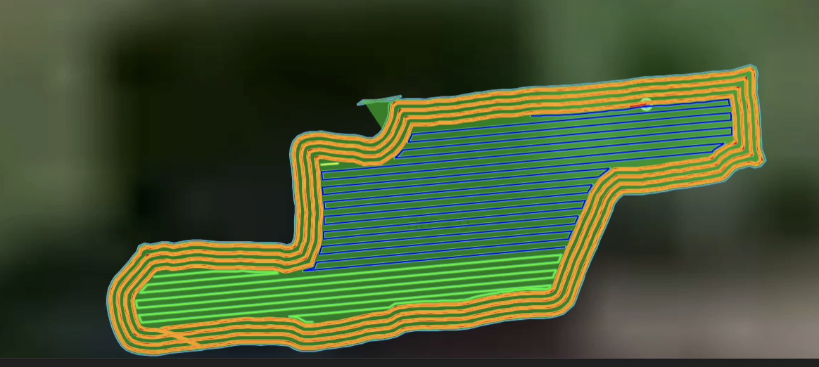
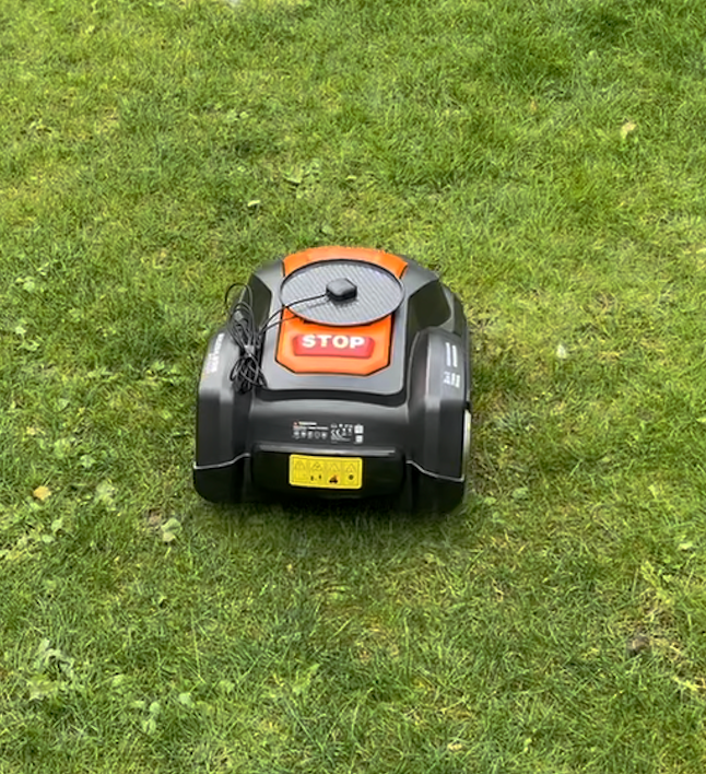
Taking it for a spin.
Once everything was done, I took the mower out for a sping outside. After getting RTK fix, recorded a small mowing area, and then launched mowing. Everything worked as expected
And the map showed the mowing path: